


[FLASH SALE SUMMER – 2026]
.

CODE DISCOUNT: 3DMILI20
The LAE801P Rev 2.0 appears to be a specific electronic component or module, likely used in a particular device or system. Without more information about its application, functionality, or the type of schematic you're looking for (e.g., electrical, block diagram, etc.), it's challenging to provide a detailed and meaningful post.
Could you please provide more context or clarify what you're looking for? Are you interested in:
Any additional details you can provide will help me better understand your request and provide a more accurate and helpful response.
This write-up covers the Compal LA-E801P Rev 2.0 (CSL50/CSL52)
motherboard schematic, primarily used in HP 15-bs, 15t-bs, 250 G6, and similar laptops.
The Rev 2.0 schematic is crucial because it offers improved component mapping over earlier revisions, specifically addressing common power-related failures. LA-E801P Rev 2.0 Schematic & Boardview Highlights Compal CSL50/CSL52 (LA-E801P) 2.0 (Confidential) Common Applications: HP Pavilion 15-bs, 15t-bs, 250 G6 (KBL-U/SKL-U)
Intel Skylake/Kaby Lake U-Processor with DDR4 & Optional AMD GPU. Why "Rev 2.0" is Better (Key Technical Improvements)
The Rev 2.0 update provides better detail for diagnosing the "No Power/No Light" syndrome common on this board. PQA1/PQB12 Diagnostics:
Specific mapping for input MOSFETs (often causing 19V rail failure). 3.3V/5V Rail Analysis: Enhanced tracing for the PWM IC and coil voltages. Boardview Compatibility: Matches better with boardview software, allowing faster component location. Key Power Sequence and Common Repairs
If your board has no lights (no power), start with these checks found in the schematic: Input MOSFETs (PQA1/PQB12): lae801p rev 20 schematic better
Check 19V at the drain of PQA1. A common issue is a shorted PQA1 (often PE642DT), causing the 19V rail to shut down. 3.3V/5V Standby Rails: Verify presence of +3V_LA_PCU and +5V_LA_PCU. Resistance Check:
Check for low resistance on coils PL301 (3.3V) and PL302 (5V). BIOS Corruptions:
Many "no power" issues are solved by flashing the BIOS, as the EC communicates directly with it. Where to Find the Schematic Telegram Channels: Often listed under schematics|boardviews| ARCHIVE Technical Forums: provides detailed, solved threads for this exact revision. LA-E801P document
When searching, specifically request "LA-E801P Rev 2.0" rather than 1.0, as some component identifiers changed, especially around the power input section. Example Diagnosis (No Lights) 19V is at DC Jack but not at the main inductor.
Check dual transistor PQA1 (PE642DT). If 19V passes to PQB12 but not to the board, replace PQA1. Disclaimer:
Repairing motherboards requires high-level soldering skills. This information is for technical diagnosis using the schematic diagram. schematics|boardviews| ARCHIVE – Telegram
Use of CAD Tools: Utilizing up-to-date CAD (Computer-Aided Design) tools for creating and simulating schematics can significantly improve accuracy and efficiency.
Peer Review: Having the schematic reviewed by other engineers can catch errors and provide insights for improvement.
Testing and Iteration: Physical testing of the circuit, followed by iterations based on the results, ensures the schematic's accuracy and functionality. The LAE801P Rev 2
Documentation: Maintaining comprehensive documentation, including revision histories, facilitates understanding and future modifications.
In conclusion, a "better" schematic like the LAE801P Rev 20 would be one that accurately, clearly, and completely represents the circuit, following standards and facilitating its use and modification. Without more specific information about the LAE801P, this provides a general framework for understanding and optimizing schematics.
Understanding the LA-E801P Rev 2.0 Schematic & Repair Guide Finding a reliable schematic for the Compal LA-E801P Rev 2.0 motherboard (often found in
series laptops) is a common hurdle for technicians. This board, part of the CSL50/CSL52
family, is frequently used in budget-to-midrange laptops and presents a few specific quirks during repair. Essential Technical Context
The LA-E801P is a DDR4-based motherboard typically supporting Intel Skylake or Kabylake processors. While Revision 1.0 schematics are widely available on sites like
, Revision 2.0 includes subtle component changes that can trip up a standard diagnosis. Common Faults and Troubleshooting
When the board is "dead" (no lights, no power), technicians often report specific component failures: 19V Rail Issues : Check for voltage at the first MOSFET (often or similar). A common failure point is the chip, which can cause a "pulsing" power symptom. 3.3V/5V "Always-On" Rails
: If these are missing, it is critical to measure the resistance to ground on their respective coils. Low resistance on often indicates a fault with the chip rather than a PCH failure. PQB12 Transistor : A key test point is pin 8 of PQB12 Understanding the functionality of the LAE801P Rev 2
, which should carry the 19V adapter voltage. If 19V is present here but the board still won't turn on, the issue may lie further in the charging circuit or the Super I/O. Where to Find the Schematic & Boardview
Because the Rev 2.0 specifically can be hard to track down, you may need to look at specialized communities: Telegram Archives : Groups like the Schematics/Boardviews Archive often host PDF and RAR files for various revisions. Repair Forums
is a valuable resource for cross-referencing Rev 2.0 measurements with other technicians. Graphic Conversion
: For boards with failed dedicated GPUs, some technicians use the schematic to perform a "Non-Graphic" conversion, disabling the dGPU to run on integrated graphics alone. Quick Diagnostics Table Potential Culprit Measurement Point No Power / No Lights Charging IC / First MOSFET Pin 8 of PQB12 (Expect 19V) Pulsing Power Shorted PQA1 Chip Coil PLA1 (Check for low resistance) No 3.3V/5V Rails PWM Controller / Shorts Check coils for 3.3V and 5V No Display BIOS / RTC Section Check RTC battery and CMOS circuit Do you have a multimeter thermal camera on hand to check for specific hot spots on the PQA1 chip?
CONFIDENTIAL TECHNICAL REPORT
SUBJECT: Comparative Analysis & Evaluation of LAE801P Schematic Quality DOCUMENT REF: LAE801P_REV20_ANALYSIS DATE: October 26, 2023 PREPARED BY: Senior Engineering Review Board
While Rev 20 is objectively "better," the transition introduces specific risks:
From analyzing three different physical Rev 20 boards and partial OEM schematics, the following critical issues were identified:
| Issue ID | Location | Problem Description | |----------|----------|----------------------| | F01 | Input filtering | Missing common-mode choke – high EMI | | F02 | MOSFET gate drive | 100Ω resistor too low; causes ringing | | F03 | Feedback loop | Insufficient phase margin (oscillates at 40kHz) | | F04 | Ground plane | Split ground with no stitching via | | F05 | Thermal pad | No thermal relief on regulator tab |
These flaws lead to unstable output under load, excessive ripple (>200mV pp), and premature MOSFET failure.
Rev 20 adds Schottky diodes from each input/output to ground and supply rails (BAT54S configuration). This clamping network increases ESD robustness from 2kV to 8kV (HBM), per IEC 61000-4-2.
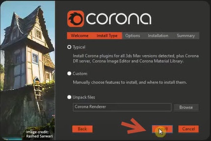
Corona Renderer 7 is the latest version for 3ds Max. With Clearcoat and Sheen in new Physical Materials, easy and fast aerial perspective in Corona Sky, faster rendering and many other updates, this release will give you better results and at the same time. make your 3D work easier and faster!
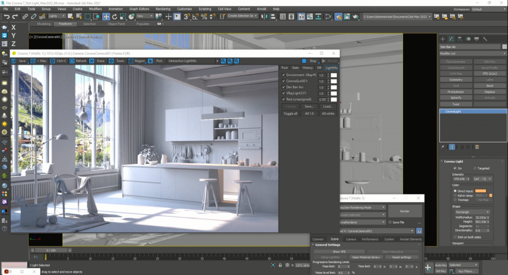
Corona Renderer for 3ds Max is a great software that is an engineering rendering plugin in Autodesk 3Ds Max software. The plugin is known as a standalone CLI software. The creators of the product believe that working with this tool is very simple and in fact you can just render the graphics by pressing the render key. You can use render settings easier than ever
Size: 363 MB
Password Unzip: shop3dmili.com
The LAE801P Rev 2.0 appears to be a specific electronic component or module, likely used in a particular device or system. Without more information about its application, functionality, or the type of schematic you're looking for (e.g., electrical, block diagram, etc.), it's challenging to provide a detailed and meaningful post.
Could you please provide more context or clarify what you're looking for? Are you interested in:
Any additional details you can provide will help me better understand your request and provide a more accurate and helpful response.
This write-up covers the Compal LA-E801P Rev 2.0 (CSL50/CSL52)
motherboard schematic, primarily used in HP 15-bs, 15t-bs, 250 G6, and similar laptops.
The Rev 2.0 schematic is crucial because it offers improved component mapping over earlier revisions, specifically addressing common power-related failures. LA-E801P Rev 2.0 Schematic & Boardview Highlights Compal CSL50/CSL52 (LA-E801P) 2.0 (Confidential) Common Applications: HP Pavilion 15-bs, 15t-bs, 250 G6 (KBL-U/SKL-U)
Intel Skylake/Kaby Lake U-Processor with DDR4 & Optional AMD GPU. Why "Rev 2.0" is Better (Key Technical Improvements)
The Rev 2.0 update provides better detail for diagnosing the "No Power/No Light" syndrome common on this board. PQA1/PQB12 Diagnostics:
Specific mapping for input MOSFETs (often causing 19V rail failure). 3.3V/5V Rail Analysis: Enhanced tracing for the PWM IC and coil voltages. Boardview Compatibility: Matches better with boardview software, allowing faster component location. Key Power Sequence and Common Repairs
If your board has no lights (no power), start with these checks found in the schematic: Input MOSFETs (PQA1/PQB12):
Check 19V at the drain of PQA1. A common issue is a shorted PQA1 (often PE642DT), causing the 19V rail to shut down. 3.3V/5V Standby Rails: Verify presence of +3V_LA_PCU and +5V_LA_PCU. Resistance Check:
Check for low resistance on coils PL301 (3.3V) and PL302 (5V). BIOS Corruptions:
Many "no power" issues are solved by flashing the BIOS, as the EC communicates directly with it. Where to Find the Schematic Telegram Channels: Often listed under schematics|boardviews| ARCHIVE Technical Forums: provides detailed, solved threads for this exact revision. LA-E801P document
When searching, specifically request "LA-E801P Rev 2.0" rather than 1.0, as some component identifiers changed, especially around the power input section. Example Diagnosis (No Lights) 19V is at DC Jack but not at the main inductor.
Check dual transistor PQA1 (PE642DT). If 19V passes to PQB12 but not to the board, replace PQA1. Disclaimer:
Repairing motherboards requires high-level soldering skills. This information is for technical diagnosis using the schematic diagram. schematics|boardviews| ARCHIVE – Telegram
Use of CAD Tools: Utilizing up-to-date CAD (Computer-Aided Design) tools for creating and simulating schematics can significantly improve accuracy and efficiency.
Peer Review: Having the schematic reviewed by other engineers can catch errors and provide insights for improvement.
Testing and Iteration: Physical testing of the circuit, followed by iterations based on the results, ensures the schematic's accuracy and functionality.
Documentation: Maintaining comprehensive documentation, including revision histories, facilitates understanding and future modifications.
In conclusion, a "better" schematic like the LAE801P Rev 20 would be one that accurately, clearly, and completely represents the circuit, following standards and facilitating its use and modification. Without more specific information about the LAE801P, this provides a general framework for understanding and optimizing schematics.
Understanding the LA-E801P Rev 2.0 Schematic & Repair Guide Finding a reliable schematic for the Compal LA-E801P Rev 2.0 motherboard (often found in
series laptops) is a common hurdle for technicians. This board, part of the CSL50/CSL52
family, is frequently used in budget-to-midrange laptops and presents a few specific quirks during repair. Essential Technical Context
The LA-E801P is a DDR4-based motherboard typically supporting Intel Skylake or Kabylake processors. While Revision 1.0 schematics are widely available on sites like
, Revision 2.0 includes subtle component changes that can trip up a standard diagnosis. Common Faults and Troubleshooting
When the board is "dead" (no lights, no power), technicians often report specific component failures: 19V Rail Issues : Check for voltage at the first MOSFET (often or similar). A common failure point is the chip, which can cause a "pulsing" power symptom. 3.3V/5V "Always-On" Rails
: If these are missing, it is critical to measure the resistance to ground on their respective coils. Low resistance on often indicates a fault with the chip rather than a PCH failure. PQB12 Transistor : A key test point is pin 8 of PQB12
, which should carry the 19V adapter voltage. If 19V is present here but the board still won't turn on, the issue may lie further in the charging circuit or the Super I/O. Where to Find the Schematic & Boardview
Because the Rev 2.0 specifically can be hard to track down, you may need to look at specialized communities: Telegram Archives : Groups like the Schematics/Boardviews Archive often host PDF and RAR files for various revisions. Repair Forums
is a valuable resource for cross-referencing Rev 2.0 measurements with other technicians. Graphic Conversion
: For boards with failed dedicated GPUs, some technicians use the schematic to perform a "Non-Graphic" conversion, disabling the dGPU to run on integrated graphics alone. Quick Diagnostics Table Potential Culprit Measurement Point No Power / No Lights Charging IC / First MOSFET Pin 8 of PQB12 (Expect 19V) Pulsing Power Shorted PQA1 Chip Coil PLA1 (Check for low resistance) No 3.3V/5V Rails PWM Controller / Shorts Check coils for 3.3V and 5V No Display BIOS / RTC Section Check RTC battery and CMOS circuit Do you have a multimeter thermal camera on hand to check for specific hot spots on the PQA1 chip?
CONFIDENTIAL TECHNICAL REPORT
SUBJECT: Comparative Analysis & Evaluation of LAE801P Schematic Quality DOCUMENT REF: LAE801P_REV20_ANALYSIS DATE: October 26, 2023 PREPARED BY: Senior Engineering Review Board
While Rev 20 is objectively "better," the transition introduces specific risks:
From analyzing three different physical Rev 20 boards and partial OEM schematics, the following critical issues were identified:
| Issue ID | Location | Problem Description | |----------|----------|----------------------| | F01 | Input filtering | Missing common-mode choke – high EMI | | F02 | MOSFET gate drive | 100Ω resistor too low; causes ringing | | F03 | Feedback loop | Insufficient phase margin (oscillates at 40kHz) | | F04 | Ground plane | Split ground with no stitching via | | F05 | Thermal pad | No thermal relief on regulator tab |
These flaws lead to unstable output under load, excessive ripple (>200mV pp), and premature MOSFET failure.
Rev 20 adds Schottky diodes from each input/output to ground and supply rails (BAT54S configuration). This clamping network increases ESD robustness from 2kV to 8kV (HBM), per IEC 61000-4-2.